Hydrogenation
System
What is Hydrogenation
Hydrogenation is one of the most critical and sensitive processes in chemical process industries for manufacturing fine chemicals and pharmaceuticals. Hydrogen gas is (liberated), at a certain temperature and pressure, into a Hydrogenator autoclave containing the process solution in the presence of a catalyst such as Nickel, Palladium, and Platinum depending on the reaction.
The hydrogen is equally dispersed through the reaction mass ensuring homogeneity. However, most of the times a substantial amount of gas remains unreacted. In order to achieve effective mass transfer, the process needs to be repeated till the reaction completes which increase batch time and energy consumption.
ACME HYDROGENATION SYSTEM
We at ACME provide a customized solution for your hydrogenation process needs. It is extremely important to not only understand the reactants involved in such processes, but also a practical understanding of the process itself. As a leading manufacturer of a wide range of agitation systems, we understand the importance of role that agitator plays.
With a holistic view, we take every element of the process into consideration:
- Maximum gas dispersion
- Maximum mass transfer
- Gas Remixing
- Catalyst suspension
- Heat Transfer
- Blending
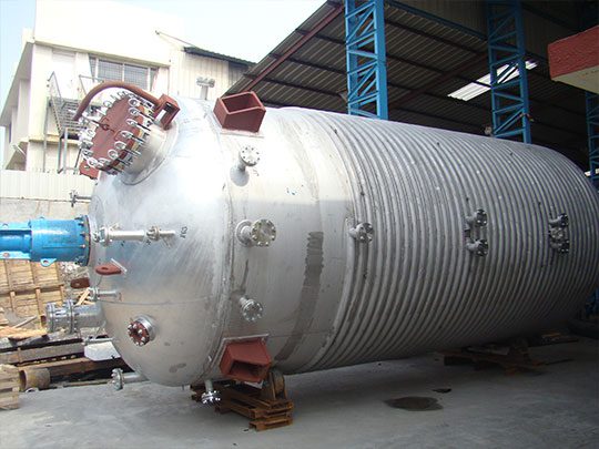
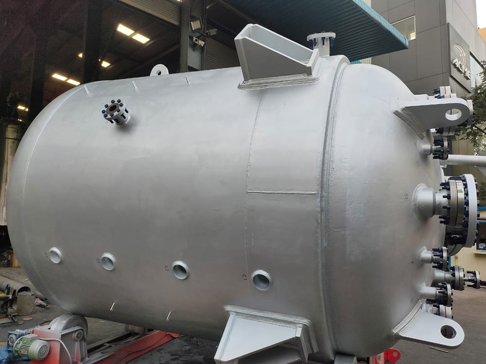
SYSTEM STRUCTURE
A typical hydrogenator includes
- Hydrogenation reactor
- Agitator
- Multiple Impellers
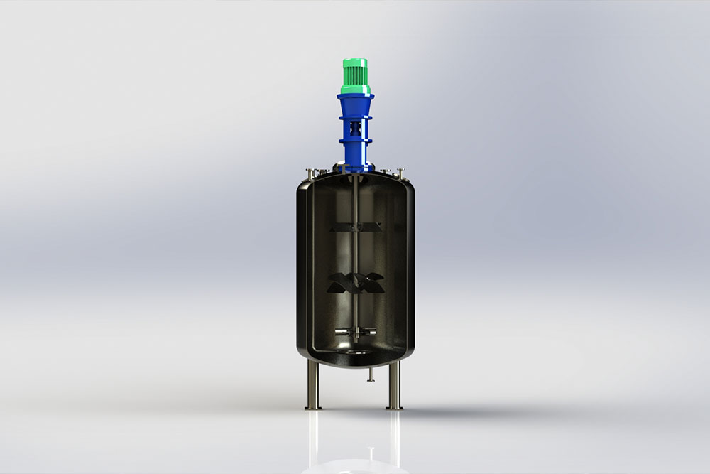
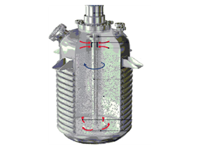
THE PROCESS
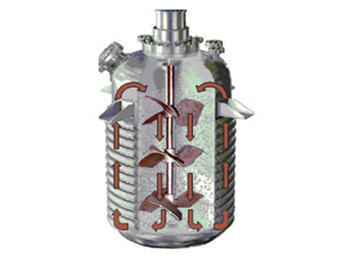
To ensure the effective contact of hydrogen gas with the reaction mass to provide required mass transfer the hydrogenator reactor is equipped with a three stage impeller system. This system helps in uniform Gas Dispersion, increasing gas holdup in liquid and maximize the utilization of gas, and reinforce the unreacted gas from the vapor space.
ACME engineers thoroughly understand the mixing mechanism and process dynamics in the Hydrogenation reactor. We provide you the right combination of impellers to achieve the desired process aspects required for the reaction.
DISPERSION
ACME CBT-601 IMPELLER
A bottom gas dispersion impeller CBT-601 located just above the hydrogen gas sparger Has a higher pumping capacity than a flat bladed turbine. It approximately maintains the ungassed power level when gas is introduced thus providing more stable operation. This improves gas dispersion which enhances the mass transfer rates thus increasing the reaction rates.
Unlike, Ruston and flat blade turbine CBT-601 does not form large cavities near the blades along the suction side of impeller which reduces the power drop up to 60% and comparatively gives better mixing performance.
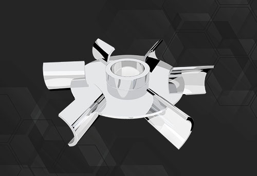
Reducing the power drop off in the gassed state implies maximum availability of power for mixing. Thus, a combination of the higher pumping capacity and lower power drop off in the gassed state will ensure good dispersion of gas and suspension of the catalyst used in the hydrogenation reaction. This impeller pumps radially so all gas hits the baffles & shell walls which reduces the bubble size in turn increasing the reaction rate due to better interfacial contact area.
HOLDING & MIXING
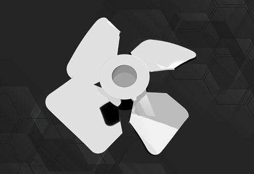
ACME AA-405 IMPELLER
This wide-bladed hydrofoil impeller AA-405 located at middle stage just above the CBT-601 impeller, gives better gas hold-up. It also provides excellent top to bottom flow which efficiently suspend and distribute the solid catalyst in the liquid. This improves mass transfer and heat transfer in the system lowering the reaction time and power input. It give same yield at a 20% less power input.
ENTRAINMENT
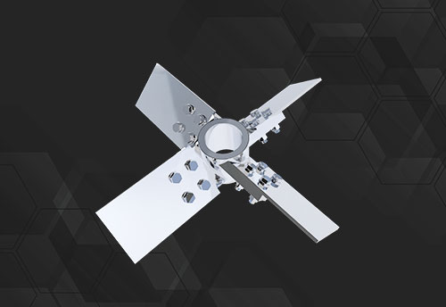
ACME PBT IMPELLER
The use of axial flow PBT (Pitched Blade Turbine) at the top stage above the AA-405 impeller, not only entrains the gas from vapor space of the vessel. This ensures more utilization of hydrogen gas and provides better flow than self-inducing upper impellers and increases the heat removal rate in the hydrogenator.
Unlike self-inducing impellers ACME™’s three-impeller-hydrogenation-agitator-system does not plug or foul.
GAS INDUCTION VS HYDROFOIL
GAS-INDUCTION TYPE
HYDROFOIL
Gas is re-induced through pipe and pushed away from impeller mixing zone. So Gas moves away from turbulence | Gas is induced below the impeller in max turbulence zone of impeller so gas bubble size is reduced |
Impeller small in size so solid suspension is not uniform throughout liquid mass | Impeller to tank Ø ratio is 0.3-0.5 so solid suspension is uniform as it is axial flow down pumping impeller |
Suction of gas in vapour space is from shaft and sparged from tip so gas velocity cannot be controlled | Velocity is controlled by sparger ring and impeller sees conducive velocity |
Gas is sparged at tip of impeller so gas is pushed away from mixing/turbulence zone of impeller at high velocity | Gas is sparged in the max turbulence zone of impeller so gas dispersion occurs throughout tank |
Continuous loop formed gas sucked and goes back in vapour space without reacting so batch time increased | Top impeller continuously changes upper liquid layer so new mass is in contact with vapour space gas every mili- second and reaction rate enhanced |
Impeller being smaller cannot hold large volume of gas in liquid mass | Impeller big and solidity high so this pressure type impeller ensures huge gas hold up in liquid mass |
Generally single impeller so re-entrainment of gas is difficult | Multiple impeller so re-entrainment of gas is very much a part of system |
Batch time observed to be higher | Batch time is 50-60 % lesser than gas-induction type impeller at same or lesser power consumption |
Combination of gas-induction with hydrofoil will help making system more efficient | Gas-induction will enhance the performance of this system |
HEAT TRANSFER
Hydrogenation reactions is an exothermic reaction, i.e., it generates a large amount of heat, which must be removed from the process. by promoting high velocity at the heat transfer source (jackets or internal coils) the lower CBT-601 and middle staged AA-405 impeller efficiently transfers the heat in the system.
EFFICIENT CATALYST SUSPENSION
Catalyst suspension plays an important role in the hydrogenation reaction. This is efficiently achieved by the high flow rate of the CBT-601 impeller and upper AA-405 and PBT axial flow impellers. An excellent top to bottom flow ensures improved suspension, re-suspension of settled solids and distribution of the catalyst throughout the hydrogenator. This enhances the mass transfer between gas- solid- liquid reaction system.
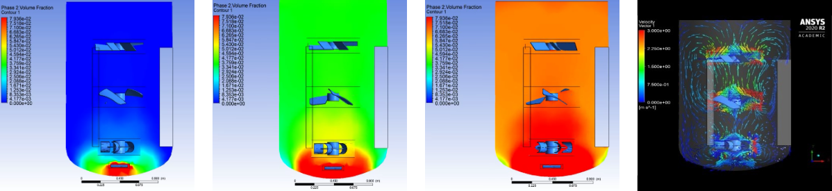
Computational Fluid Dynamic simulation is done to study the distribution of gas in the reaction mass. This simulation can predict through distribution of gas in the reaction mass over the time, the velocity vectors of gas as well liquid, performance of each impeller in the reactor, dead zones. Study of these predictions helps to improve the process results.
BENEFITS
- Improves mass transfer
- Complete consumption of Hydrogen gas
- Improves Productivity exponentially
- Substantially Saves Energy
- Significantly reduces the process time
- Enhances catalyst life
Since more than a decade, ACME Engineers have been guiding their clients. For selecting the correct impeller system and accurate design of power/volume. Our high profile clients have achieved tangible benefits through our process knowledge and our three-impeller hydrogenation agitator system design.
SAVE ENERGY | IMPROVE EFFICIENCY | ACHIEVE SUSTAINABILITY
Through ACME’s Hydrogenation Engineering
Our Clients
They Believe In Us